
Majevička 164, 76300 Bijeljina, Bosnia and Herzegovina
+387 66 395 698 · +387 65 222 957 · office@weldon-bn.com · weldon-bn.com
Installation rules and length calculation
The right installation form and an accurate minimum length calculation ensure full effect and a long service life of the hose.
Besides conveying media where rigid steel pipes cannot be used, corrugated hoses are applied for:
- eliminating the effects of inaccuracies in rigid pipelines,
- compensating parallel offset of pipelines,
- absorbing angular movement,
- absorbing multi-directional, small-amplitude, high-frequency vibrations from machines and equipment,
- absorbing vertical and horizontal movement of one or both pipe legs,
- absorbing thermal expansion of rigid pipelines.
For a long service life the installation form must avoid multi-directional vibration: forces must act perpendicular to the hose axis and the system must lie in one plane to exclude dangerous torsional stress.
Installation form A
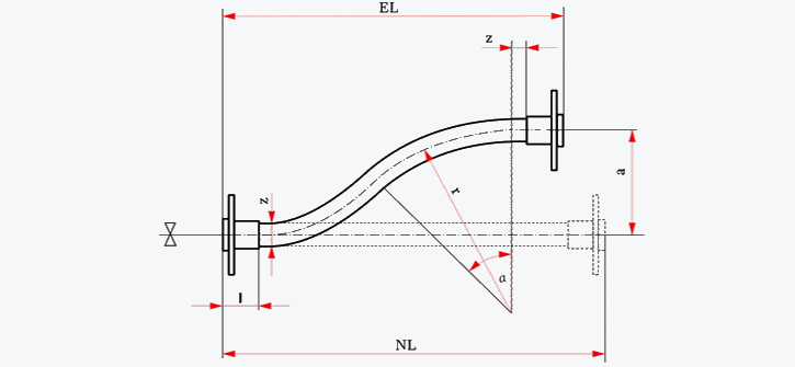
To eliminate the effects of inaccuracies in rigid pipelines and to compensate for parallel offset. The bending angle must not exceed 45° for braided and 60° for unbraided hoses.
| DN | ≤ 12 | 16 – 25 | 32 – 40 | 50 – 65 | 80 – 100 | 125 – 150 |
|---|---|---|---|---|---|---|
| z (mm) | 25 | 50 | 75 | 100 | 150 | 200 |
Installation form B
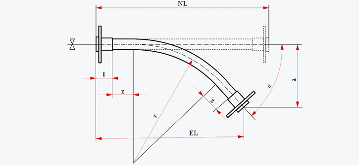
To compensate for inaccuracies of rigid pipelines and for angular movement. Bending angle up to 45° for braided and up to 60° for unbraided hoses.
| DN | ≤ 12 | 16 – 25 | 32 – 40 | 50 – 65 | 80 – 100 | 125 – 150 |
|---|---|---|---|---|---|---|
| z (mm) | 25 | 50 | 75 | 100 | 150 | 200 |
Installation form C
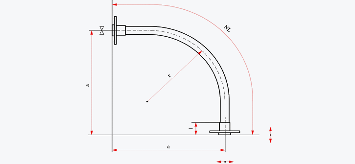
To absorb multi-directional vibrations of small amplitude and high frequency from compressors, pumps and engines. Forces act radially to the hose axis; direction of movement and hose bend lie in one plane, avoiding dangerous torsion.
Installation form D
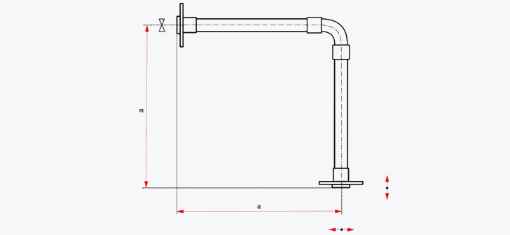
To absorb vibrations on large sizes (DN 125 and DN 150): two hose legs connected by a rigid elbow.
Installation form E
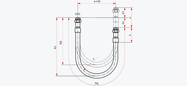
For vibrations of large amplitude and low frequency. The legs are connected at 180° with one moving leg in vertical direction. Both legs and the movement must lie in one plane.
Installation form F

For vibrations of large amplitude and low frequency with the moving leg in horizontal direction (lateral movement). Legs and movement lie in one plane.
Installation form G
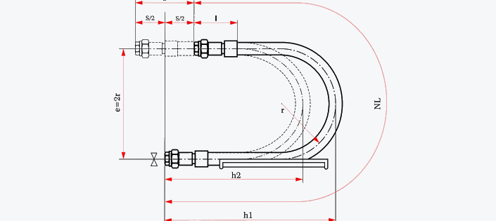
For vibrations of large amplitude and low frequency with the moving leg along its own axis (horizontal loop). Legs and movement lie in one plane.